Structure of a MINERVA project#
MINERVA projects can include multiple files, allowing to pre-configure a number options and functionalities. The structure explained below can be either compressed into a .zip file or uploaded from a git repository. See this repository for example.
The list of project components is as follows:
- root diagram (file, mandatory)
a systems biology diagram in one of the compatible formats: CellDesigner SBML, SBML, SBGN-ML, or GPML, see compatible formats. - submaps (folder, optional) - see Submaps
- any number of compatible systems biology diagrams (file(s))
- mapping of links between diagram elements and submaps (file in CellDesigner SBML format, default name: mapping.xml)
- overlays (folder, optional) - see Overlays
files with data overlays to be set as publicly visible for the project, see more in visualisation - glyphs: directory with glyphs (see Glyphs)
- images: directory with files displayed as Browse overview images (see Images)
Learn more about advanced upload in example 04 - The advanced file upload.
Sections of the structured project#
Submaps and mapping file#
The submaps subdirectory contains files that will be displayed in the Submaps tab in the functional area of the User view (see section User view - Submaps tab). Additionally to the submaps files, one additional file - submap mapping file, can be added to the directory. This file describes connections between the submaps and the main map itself.
Submap mapping file is a CellDesigner file, in which relations between the uploaded maps are represented graphically. Two types of components and one type of interaction is considered when parsing this file:
State transition reaction describes relations between components of the map.
Complex should be named as a map file (the main map, or a submap), but without the .xml extension.
Protein should be named as an alias of referred element in the source file (the main map, or a submap). Please note that a species alias is not the same as a species identifier!
Remark: alias vs identifier**#
CellDesigner has a single species identifier for all copies of a certain element (e.g. protein) in a file.
If you open your CellDesigner file in any text editor you can find it in species tag, parameter id:
<species metaid="s1" id="s1" name="SNCA" compartment="default">
Different instances of the same element (here: ‘s1’) have different species aliases, so they can be distinguished in the model. MINERVA uses this alias to link specific map element (anchor) with the submap.
You can find species alias of element if you open your CellDesigner file in any text editor, then find tag speciesAlias for particular species id (here: ‘s1’):
<celldesigner:speciesAlias id="sa1" species="s1">
<celldesigner:speciesAlias id="sa2" species="s1">
To facilitate work with the submaps, we created CellDesigner plugin which provides species alias in CellDesigner (no need to look for an alias in text editor). You can download plugin (here). Paste the plugin into directory “plugin” inside CellDesigner folder (i.e. CellDesigner4.4.2/plugin). Now, you can start using the plugin. Open your project in CellDesigner and press keys “Control + T” on any highlighted protein to display its alias (dialog, see below, will open).
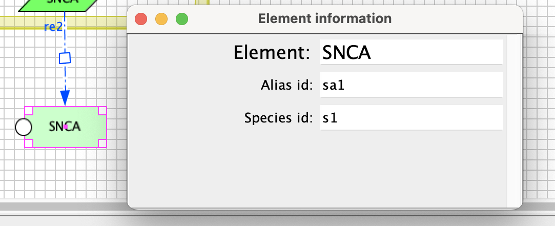
Image below demonstrates an exemplary submap mapping file.
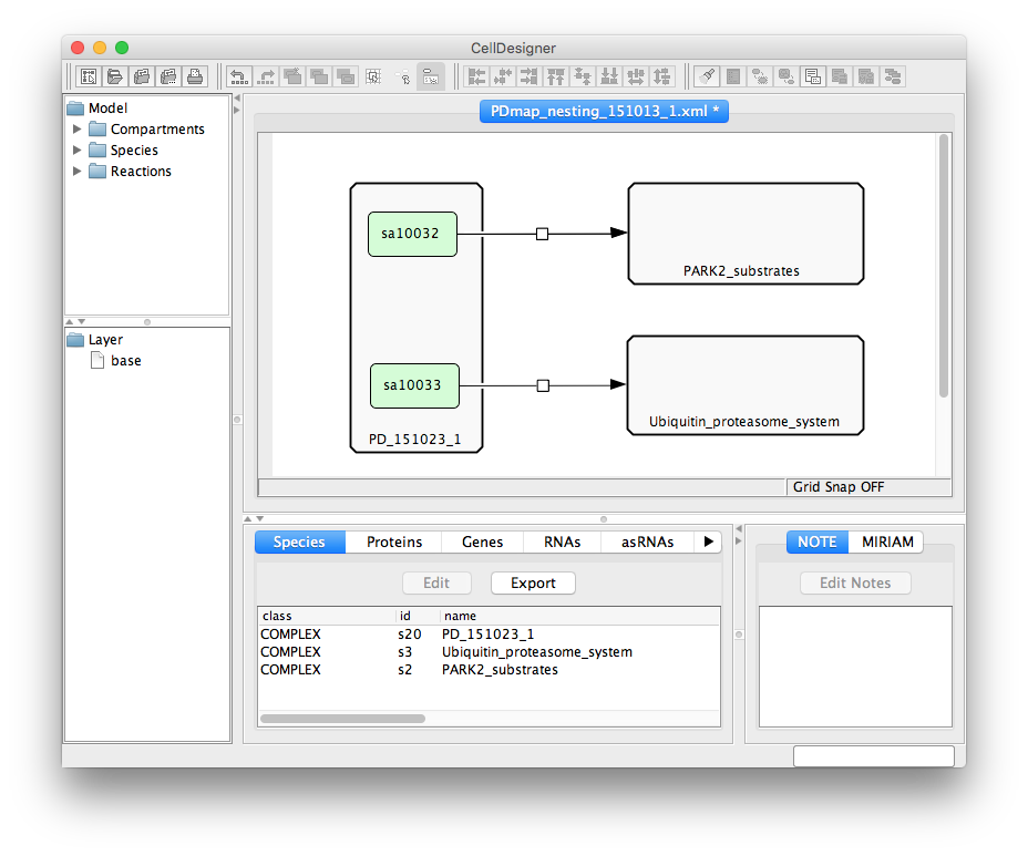
On project upload (see here), the dialog window will show uploaded diagram, the file considered as a root diagram, and the file considered a mapping file.
Overlays#
The overlays subdirectory contains files with custom colouring of the uploaded content that will be accessible to all the users. The format is identical to the format of files uploaded by registered users. See section Upload user provided overlay data for details on file format.
Glyphs#
Glyphs are custom images that can be added to diagrams visualised in the MINERVA Platform. The image of any element of the diagram (species, compartment, pathways) can be replaced with such custom images (see below).
Size and format Glyphs will be resized to fit the size and aspect ratio of the element they are assigned to.
MINERVA supports only .png images as glyphs.
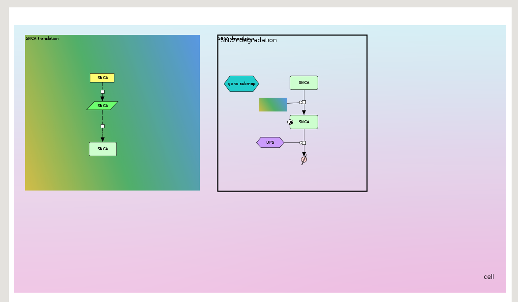
Diagram elements can be assigned a glyph from this directory directly on project upload. To do so, <notes> tag of the .xml file with the diagram has to contain the following string, or add this text in the Notes section in the diagram editor.
Glyph: glyphs/my-image.png
For CellDesigner text area (converted to Pathway object in MINERVA), the text should be added directly as the title.
Find more details about glyphs in the example 6 - Map with glyphs.
Images#
The images subdirectory contains static image files in .png format that will be displayed after pressing the Show overview button (see Browse overview images in User manual). Besides the images, the directory also has to contain a file describing links between the images and the associated network(s). This file must be a tab-separated text file named coords.txt or json file named coords.json.
The coords.txt file is a table with the following structure:
FILE - linked image file.
POLYGON - a sequence of points in the linked image file forming a polygon, which will be treated as an active area for the link. The points should be
x,ypairs separated by a spacebar, representing absolute coordinates of the pixels in the corresponding image. They should be provided in a single line.LINK_TYPE - the type of link to the image, has to be one of the types specified below; link type determines the usage of the remaining fields.
IMAGE - links to another image of the uploaded set.
MODEL - link to the main map, or one of the submaps.
SEARCH - link to the results of a search query.
LINK_TARGET - determined by the field
LINK_TYPE.if IMAGE - filename, must be one of the uploaded image files in the images directory.
if MODEL - filename of the uploaded main map, or one of the submaps.
if SEARCH - query to be executed and linked (see section Search in User manual).
MODEL_COORDINATES - if the field
LINK_TYPEisMODEL, this field should contain absolute coordinates of the point in the target map, in the formatx,y; otherwise it should be left empty.MODEL_ZOOM_LEVEL - if the field
LINK_TYPEisMODELand absolute coordinates are given, this field should contain a number corresponding to the zoom levels in the display area; otherwise it should be left empty. The the furthest zoom out has number 0, each zoom in increases the zoom number by one. Smaller maps will have less zoom levels than big ones. Try uploading the map without images first, and assess the coordinates and zoom levels for the version with images.COMMENT - a field for supplementary information, not used for configuration.
Example of a coords.txt file:
| FILE | POLYGON |
LINK_ TYPE |
LINK_ TARGET |
MODEL_ COORDINATES |
MODEL_ ZOOM_LEVEL |
COMMENT |
|---|---|---|---|---|---|---|
| image-A.png | 51,218 107,218 107,252 51,252 | MODEL | PD_151023_1.xml | 7488,11986 | 4 | Links image-A to a point in the diagram with zoom level 4. |
| image-B.png | 15,187 73,187 73,52 15,52 | IMAGE | image-A.png | Makes image-B file to show image-A. | ||
| image-C.png | 30,8 10,8 10,7 30,7 | SEARCH | reaction:c1,reaction:c2 | Links image-C to results of search for reactions c1 and c2. |
The coords.json file structure:
filename - linked image file.
links - an array describing a link between image in filename with imageLinkFilename, query or modelLinkFilename.
polygon - the coordinates of the polygon which will be treated as an active area for the link. Provide absolute coordinates of the pixels in the corresponding image.
imageLinkFilename - links to other image form uploaded set, provide file’s name.
query - link to the results of a search query, provide the query.
modelLinkFilename - link to the main map, or one of the submaps.
zoomLevel - in case of linking to modelLinkFilename - this field should contain a number corresponding to the zoom levels in the display area; otherwise it should be left empty. The the furthest zoom out has number 0, each zoom in increases the zoom number by one. Smaller maps will have less zoom levels than big ones. Try uploading the map without images first, and assess the coordinates and zoom levels for the version with images.
modelPoint - in case of linking to modelLinkFilename - this field should contain absolute coordinates of the point in the target map, otherwise it should be left empty.
Example of a coords.json file:
[
   {
      "filename":"test.png",
      "links":[
         {
            "polygon":[
               {
                  "x":10.0,
                  "y":10.0
               },
               {
                  "x":100.0,
                  "y":10.0
               },
               {
                  "x":100.0,
                  "y":100.0
               },
               {
                  "x":10.0,
                  "y":100.0
               }
            ],
            "imageLinkFilename":"sub_image.png"
         },
         {
            "polygon":[
               {
                  "x":120.0,
                  "y":120.0
               },
               {
                  "x":150.0,
                  "y":150.0
               },
               {
                  "x":120.0,
                  "y":150.0
               },
               {
                  "x":150.0,
                  "y":120.0
               }
            ],
            "query": "s3,reaction:re1"
         }
      ]
   },
   {
      "filename":"sub_image.png",
      "links":[
         {
            "polygon":[
               {
                  "x":200.0,
                  "y":200.0
               },
               {
                  "x":200.0,
                  "y":400.0
               },
               {
                  "x":400.0,
                  "y":400.0
               },
               {
                  "x":400.0,
                  "y":200.0
               }
            ],
            "zoomLevel":1,
            "modelPoint":{
               "x":10.0,
               "y":100.0
            },
            "modelLinkFilename":"main.xml"
         }
      ]
   }
]