Layers#
Layers provide an additional level of annotation on top of diagrams, highlighting specific areas or guiding users though the content.
Layer contents can be exported with the rest of the diagram using the Download generated zip button in the project info panel.
Adding a new layer#
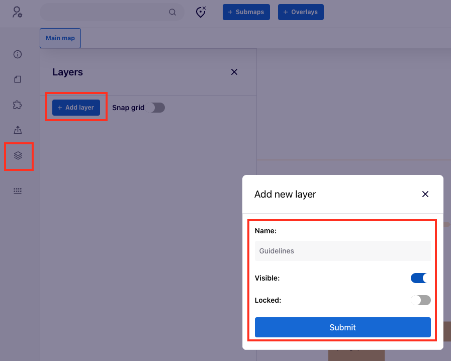
They are accessed by using the Layers button in the left menu. Administrators of a given MINERVA instance and curators of a given diagram can add and configure multiple layers.
New layers are set up using the “Add layer” button. The popup will allow to define the name of the layer, and if it should be visible to all users by default. “Locked” toggle makes the layer non-editable by default, and it will have to be unlocked manually for each edit.
Layer configuration#
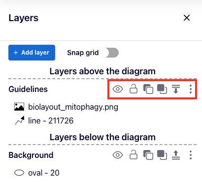
After adding layers, they can be configured. Layers are grouped into “Layers above the diagram” and “Layers below the diagram”.
Elements of layers above the diagram are shown over the content of the diagram. Elements of layers below the diagram are masked by the diagram. This can be changed by using the ![]() and
and ![]() .
.
Relative positions of layers within the same group are controlled by ![]() buttons within the line of layer control buttons.
buttons within the line of layer control buttons.
Layer components#
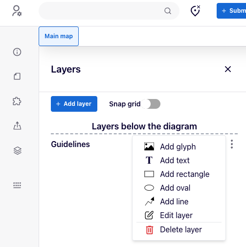
Components can be added to a layer by using the ![]() button. Available components are:
button. Available components are:
- glyph add user-defined image. Glyphs support transparency, and can have up to 1MB. Original proportions of the image are preserved.
- text add text labels with defined font size, horizontal and vertical alignment, color, border color and thickness
- rectangle and oval with defined fill color, and border color and thickness
- single or multi-segment line with defined color and width, line type, and start and end arrows.
After adding components to a layer, they can be edited using the following strip of buttons: ![]() .
.
From left to right, these buttons 1) center to the element, 2) edit the component, 3 and 4) change relative order of the elements within a layer, and 5) remove the component.
Snap to grid toggle enables this functionality for elements added to all layers.
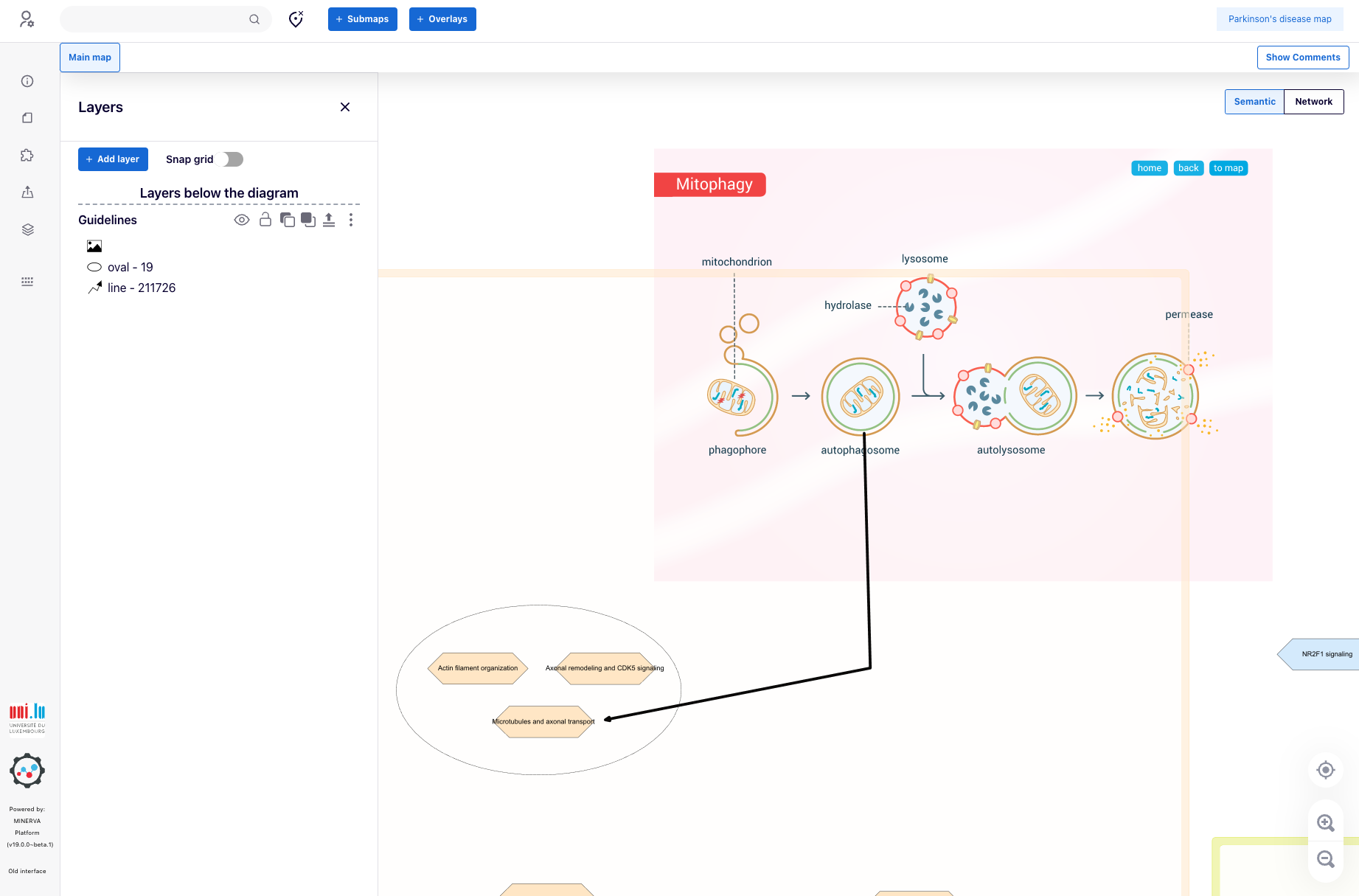
Layers - an example#
Below is an example of two layers, one above the diagram and one below. The top layer contains a custom image and a two segment arrow, the bottom one contains an oval.
The oval is not masking the diagram components because it belongs to layers below the diagram.
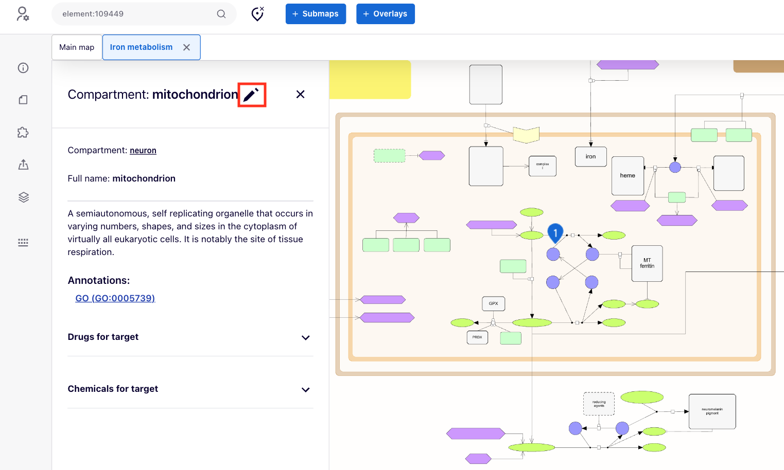
Compartment glyphs#
Independently of defined layers, custom look of compartments can be configured by administrators or curators of a project (see user roles). For these users, a pen icon ![]() is available next to the name of a selected compartment. It invokes a menu to upload, edit, or clear a glyph for a given compartment.
is available next to the name of a selected compartment. It invokes a menu to upload, edit, or clear a glyph for a given compartment.